Making myself design a PCB for the comma.ai Challenge in under 24 Hrs
Oct 12, 2026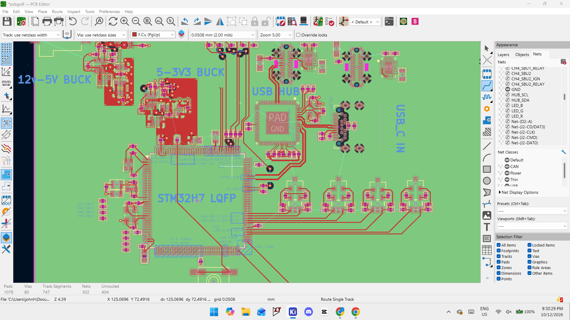
If you don’t know them, (pull up a browser now), comma.ai is a pioneering ai and self-driving company run by George Hotz, whom is also known for various “hacks”. They’ve made Openpilot, a L2 operational self driving software that is a really nice open-source version of the things that other automotive manufacturers keep behind closed doors.
The essence of the challenge https://github.com/commaai/PCBGolf is to
- Design a PCBA based on their (panda jungle v2) and a parts list
- Make the pcb manufacturable by jlcpcb
- Make sure it works (even passingly)
- Add the
- Make any modifications you need(hardware, firmware, jailbreak) anything goes
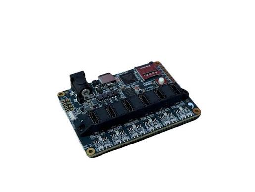
Since GPT Astra’s release, the jury is out on whether or not ia will replace PCB Designers so this seems like their attempt at producing an independent answer.
Since the deadline was at 11:59 PM EST, I made some calls and blocked off a solid 12 hrs to sit down and try to get something working.
A Fool and his Time
Like the start of any good story, I started by wasting some time, since time was clearly something I had a lot of. Analyzing the formula to compute final score,
$f(x) = whl + 50N_vias + 5000N_layers$, I did some quick mental maths.
Looking at the leaderboard at the time high score of 13,000 I quickly figured out that someone had managed to make a working 2 layer board. However, I still decided on using a 4 layer board since I knew myself well enough to know that I wasn’t doing a 2 layer anytime soon.
Interestingly enough, the bounding box term of whl also made me consider horizontal mounting of the usb connectors but I ultimately ditched that thought for more pressing matters.
The Sharpest Tool in the Shed
That’s me by the way. I had accumulated perhaps a 100 hour or so in KiCad, about 5 hours in Altium Designer, and 3 hrs in Cadence Virtuoso as a result of school. It was a no-brainer.
I also knew that there was an Autorouter plugin which I wanted to use again (subtle foreshadowing). More importantly, I wanted to do things right this time around instead of fudging things up.
The plan
- Understand the block diagram of the schematic
- Look at past “pandas” to get a baseline of how the components were layed out to avoid excessive # vias
- Start layouting Power, high speed traces, etc.
- Get the autorouter to do the rest
- Cut down board dimensions and submit!
Hour by Hour Breakdown
9:00 AM
The schematic is nicely sorted into subsheets (nice) of Power, STM32H7, USB+SD, CAN-FD, and Channels.
Luckily, I had enough EE knowledge to recognize the AP62300T Buck converters and spent some time admiring the protection circuitry like the TVS and P-type RPP. What can I say? It’s cool.
I pulled up the datasheet quickly and made a mental note of their recommendations for the layout.
Although I had analyzed DC-DC converters in Spice, I never layed one out before so I knew that this would take some time. The schematic for the STM32H7 (w0w) was relatively straightforward to understand other than the smattering of net labels. I had previously also encountered USB-C ports, hubs, and microSDs in a RP2040 design guide so I skipped through those as well. Next, for the CAN-FD, I knew about the transceiver and it was easy enough to deduce the comparator LED or what have you. Finally, for channels, I had to search up what a TPS25942 is. It’s a eFuse MUX which is a nifty little IC. The one circuit that took some time to figure out is the Ignition and Relay subcircuits which basically just simulate electronic controls from the STM32.
11:00 AM-12:00PM
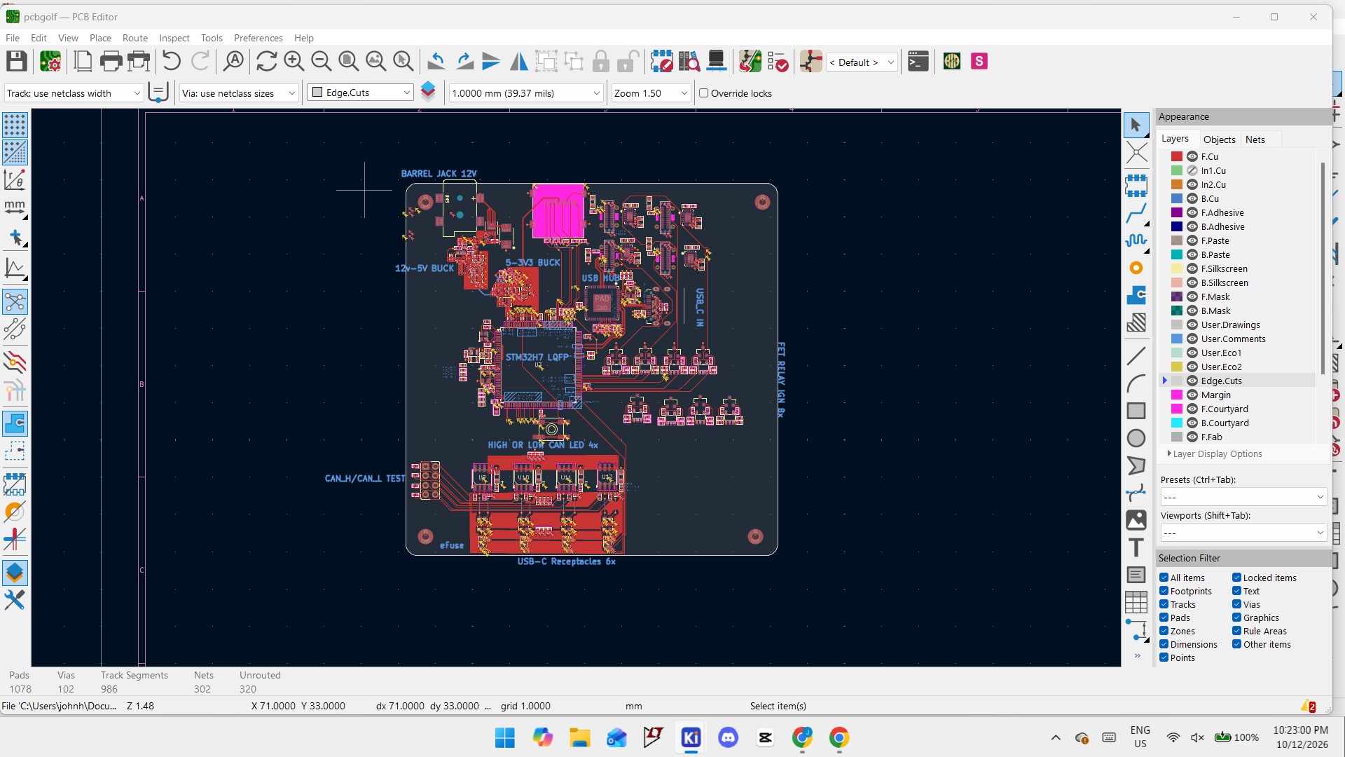
By noon, I had started laying out the PCB. I first centered the STM32H7 and made the edge cut rectangle. I wrangled together the stackup with solid ground planes on L2 and L3 for the buck converter. With all that out of the way and a hot cup of water, I started with the power path namely the 12V->5V->3V3. Some key notes that I either knew from books or from research.
- TVS Diode should be as close to the source as possible
- Bypass capacitors should be as close to the pins of the uC as possible
- Vias are needed for thermal relief and for a connection to the solid ground plane.
- Parallel signals can cause crosstalk and chatter, affecting sensitive timers and the like
12:00PM-1:00PM: What goes up must come down
I started by arranging the related nets together for the Buck converters. Studying the reference sheet, I quickly figured out how to make the Planes as well as add those aesthetic edges. Who said CAD couldn’t be helpful? This took some time but I figured that I would just copy the schematic for the first to the second. I got something somewhat reasonable in the first hour and then I looked up how to clone designs but I couldn’t figure out the menus so I decided to do things the old-fashioned way yet again.
1:00PM-3:00PM: Time’s Up!
Nope. But it was definitely starting to get a little tight. I pieced together the External crystals (again with 2 mm) of the uC and the Hub. I also played around with the bypass capacitors and generally did some of the easier tasks. I also connected the 120-Ohm termination resistors between the CAN_L and CAN_H and hooked up the microSD card pins. I took quick break for lunch where I discovered that there was no one on campus.
3:00PM-4:00PM: Pins, pins, and more pins.
I experienced a tinge of nostalgia thinking about the last time I did a pcb design with the slightly dated but excellent ATMega328p with its 32 QFN pins and cringed a little at how I felt that was “complex”. Just the way learning goes, I guess. I experienced the bright idea of using User.Comments to write out the main blocks of pins so I could figure out how I wanted to orient the uC and the main subsystems around it. I also reconfigured some pins in the schematic to prevent the use of those nasty vias.
4:00PM-5:00PM: The wheels on the Universal Serial Bus go insert RUNing guy ->
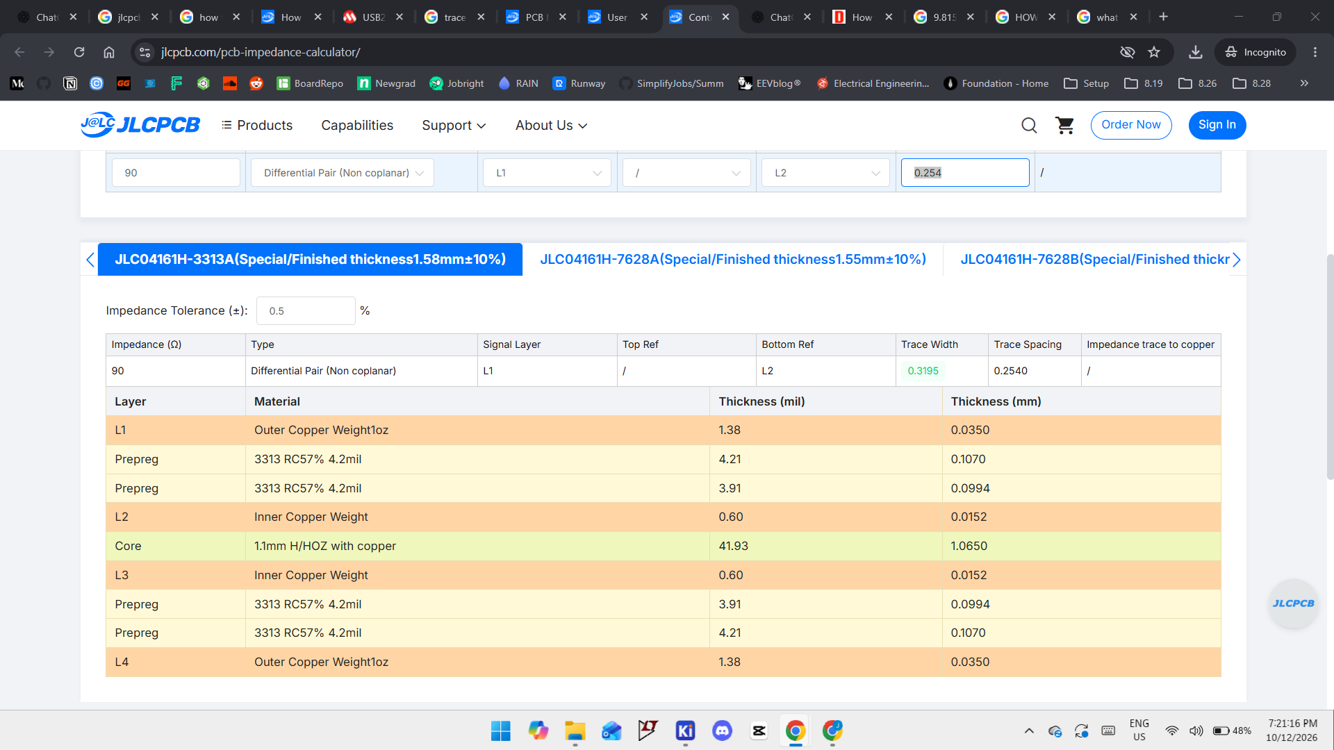
I did a quick calculation for Trace width on jlcpcb’s handy calculator which gave me the necessary requirements to achieve a smooth 90 ohms of «Controlled impedance». Who doesn’t like control? I calculated the skew (very scientific) to be 0.3mm which is under the 3mm that AI says USB-C can tolerate. Thanks Sam Altman. I also took a quick little browser surfing break and downloaded some pdfs on designing high speed circuits which added some more lost time.
I spent some time understanding the key parameters such as Microstrip vs Stripline, dielectric constants, and looked at some pretty radiating pictures of EM radiation.
Anyways, I edited those Net Classes and then had the pleasure of finding out that there was absolutely no way I was routing two 0.31mm wide chungus traces in about as much space as Harry Potter had to store his schoolbag.
5:00-7:00PM
At this point, I was pretty aware of the challenges needed to finish this challenge. I hadn’t even gotten to the packaging component; ie making a case. I ran a quick DRC and boom; 500+ errors on the DRC and probably an equal number of warnings. Realistically half of the errors were caused by improperly set minimums on KiCad or silkscreen overlaps.
7:00PM-10:00PM
I kept grinding away at this
10:00PM-11:00PM: Wrapup :)
Takeaways and what I learned
- Get comfortable with shortcuts. Carpal tunnel ain’t fun and it definitely ain’t pretty to look at.
- References are your friend. There’s no need to reinvent the wheel and definitely no need to reinvent the buck converter.
- Foresight matters a lot. 1 minute of planning can be the difference between 1 hour of work.
A number on a leaderboard would be nice but realistically participating was super helpful in rekindling my interest in pcb work. Im still waiting for Sam to come up with something new but until then, Im still happy to keep trying my luck at this.
To be honest, I will follow up with what I submitted and see in two months if I can fix it up. For now, its still at a sad 495 errors in the DRC but it could be worse. Ha
I’m interested in the winning submissions and eager to learn from their designs, so stay tuned for more long form blogs like this.